DS620 Digital Thermometer and Thermostat
2 of 15
PIN DESCRIPTION
PIN
NAME
FUNCTION
1
SDA
Data Input/Output Pin for serial communication. Open drain. (No diode connection to V
DD
).
2
SCL
Clock Input Pin for 2-wire serial communication.
3
PO
Programmable Output Pin. Open drain. (No diode connection to V
DD
).
4
GND
Ground Pin.
5
A2
Address Input Pin.
6
A1
Address Input Pin. Also serves as an input to trigger one-shot conversions during standalone use.
7
A0
Address Input Pin.
8
V
DD
Supply Voltage Pin. +1.7V to +3.5V power supply pin.
PAD
PAD. Connect to GND or float. DO NOT CONNECT TO SUPPLY. The exposed pad is the best way to conduct
temperature into the package. Connecting PAD to a ground plane can assist in properly measuring the
temperature of the circuit board.
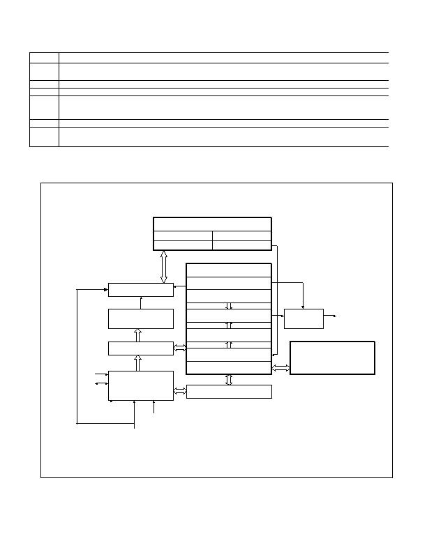
Figure 1. Block Diagram
Memory Array
2-Wire Interface
Charge Pump
Temp. Core
Bandgap
ADC
POR
Digital Control
PO Pin
Control
Address Counter
Address/Command
Decode
Conversion Control
Configuration Register
TH, TL Registers
Digital Comparator
Temperature Register
User EEPROM Registers
Temperature Counter
Memory Interface Logic
PO
SCL
SDA
A2
A1
A0
DS620
发布紧急采购,3分钟左右您将得到回复。
相关PDF资料
DS7505U+T&R
IC DGTL THERMOMETER 2WIRE 8-USOP
DS75LVU+T&R
IC SENSOR TEMP DIGITAL 8MSOP
DS75LXS+
IC THERMOMETER/STAT DIG 8-SOIC
DS75U+T&R
IC THERMOMETER/STAT DIG 8-MSOP
FAN4010IL6X_F113
IC CURRENT SENSE 0.2% 6MLP
FAN5069EMTCX
IC REG DL BCK/LINEAR 16TSSOP
HIP1011BCB-T
IC CTRLR HOT PLUG PCI 16-SOIC
HIP1020CK-T
IC CTRLR HOT PLUG SOT23-5
相关代理商/技术参数
DS620U+T&R
制造商:Maxim Integrated Products 功能描述:TEMP SENSOR DGTL 2-WIRE 8USOP - Tape and Reel 制造商:Maxim Integrated Products 功能描述:IC THERMOMETER/STAT DIG 8MSOP
DS620U+T&R
功能描述:板上安装温度传感器 Low-Voltage .5+/-C RoHS:否 制造商:Omron Electronics 输出类型:Digital 配置: 准确性:+/- 1.5 C, +/- 3 C 温度阈值: 数字输出 - 总线接口:2-Wire, I2C, SMBus 电源电压-最大:5.5 V 电源电压-最小:4.5 V 最大工作温度:+ 50 C 最小工作温度:0 C 关闭: 安装风格: 封装 / 箱体: 设备功能:Temperature and Humidity Sensor
DS6216FR000
制造商:Thomas & Betts 功能描述:60A,REC,2P3W,MG,216,208V
DS6216FRAB0
制造商:Thomas & Betts 功能描述:60A,REC,2P3W,MG,216,AB0,208V
DS6216MP000
制造商:Thomas & Betts 功能描述:60A,PLG,2P3W,MG,216,208V
DS6216MRAB0
制造商:Thomas & Betts 功能描述:60A,NLT,2P3W,MG,216,AB0,208V
DS62401TLG
制造商:ADV 功能描述:ADVANCED 24pin IC SOCKET NXE8C
DS624-01TLG
制造商:ADV 功能描述:ADVANCED 24pin IC SOCKET NXE8C 制造商:Advanced Interconnections Corp 功能描述:DIP24, IC SOCKET